Dipoles are one of the first antennas ever created. Indeed, Hertz himself is often credited as the inventor of the dipole, 1886). It’s also the simplest antenna designs out there while staying very powerful and useful, in all bands.
Dipole antennas are “two-sided’ in that they are fed from a point between the two ends. In its simplest form, a dipole will be center-fed, with the total length being a half-wavelength at the frequency of transmission.
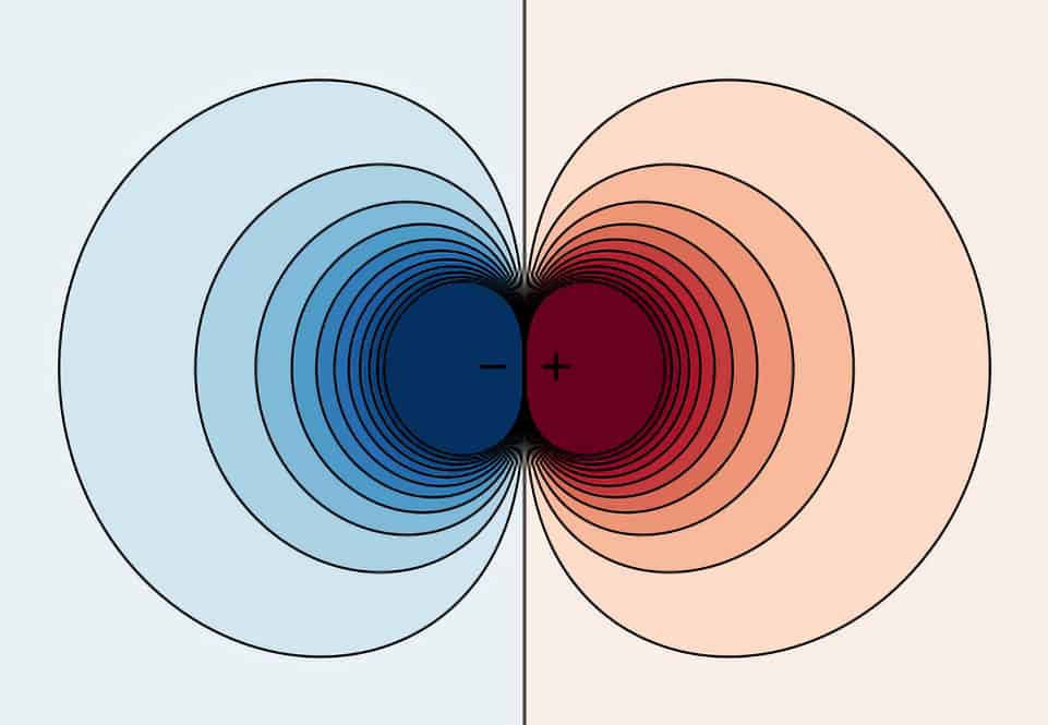
Centre-fed half-wave dipole
Half-wave center-fed dipoles with each leg 1/4 wavelength long are perhaps the most common antennas used in amateur radio. They are an example of a balanced antenna which does not require a counterpoise or other RF ground.
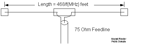
However, in the above diagram, the coaxial cable is not a balanced feeder because the outer shield is grounded and therefore the feedline itself can radiate. This can be solved by using a balun.
These 1/2 wave dipoles can be used on their odd harmonics as well as their fundamental resonant frequencies. For example, the amateur 40-meter band begins at 7 MHz. The 3rd harmonic is 3 x 7 = 21 MHz, where the 15-meter band begins. Thus a center-fed dipole that is a half-wavelength long at 40 meters (approximately 20 meters long, or 66 feet) can also be used as a 15-meter antenna.
Dipole length for resonance is calculated using either:
<math>L = \frac {468}{frequency(MHz)}</math> for total length in feet, or,
<math>L = \frac {142.5}{frequency(MHz)}</math> for total length in metres.
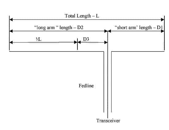
Off-center-fed dipole (OCF dipole)
As the name suggests, the OCF dipole is not fed from the center. The advantage of a 1/2 wave OCF dipole fed 1/3 of the way from one end is that it can be used on the fundamental frequency and its even harmonics.
Since most amateur bands are even harmonics of other amateur bands, this is a useful feature. An OCF that is 1/2 wavelength long on 80 meters (40 meters long, or 132 feet) can be used on 80, 40, 20, or 10 meters.
L is calculated from the formulae above. The dimensions D1, D2 and D3 are found using:
<math>D1 = 0.38L</math>
<math>D2 = 0.62L</math>
<math>D3 = 0.14L</math>
G5RV antenna
Although the G5RV is not a 1/2 wave dipole like those described above, this antenna (invented by Louis Varney, callsign G5RV) shares some physical characteristics with a center-fed dipole. The main difference between a dipole and G5RV is that the transmission line of a G5RV is part of the matching section that allows operation over a number of bands. Although the G5RV can be used on 20 meters without an antenna tuner, a tuner is necessary to use it on other bands.
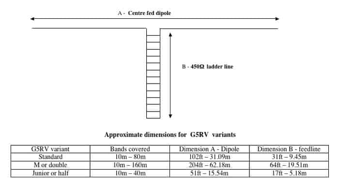
There are several different variations on the G5RV. The most well-known is fed through 450-ohm ladder line 10.6 meters (34.8 feet) long, with one end of the ladder line connected at the center-feed point of the antenna and the other connected through a balun to 50-ohm Coaxial Cable feedline. An alternative is to run balanced feedline (such as twin-lead or ladder line) all the way from the antenna feed point to the antenna tuner. The latter arrangement can be very effective, but not all lengths of feedline will tune properly. (See detailed discussion on feedlines.) Standard G5RV antennas are 31 meters (102 feet) long (excluding feedline and matching section length), and can be used on 80, 40, 20, 15, and 10 meters. A half-length G5RV 51 feet long can be used on 40, 20, 15, and 10; this variation is known as the G5RV jr.
The antenna can be installed as a horizontal dipole or an inverted V. If configured as such, the included angle at the apex should exceed 120 degrees. This means, for example, that a junior G5RV will be elevated at most 13 feet higher than the ends of the dipole. To calculate this, you can use the following, where we split the triangle created by the inverted V in two square triangles to apply simple trigonometry:
<math>\frac{height}{hypotenuse} = \cos(half of included angle)</math>
hence:
<math>height = hypothenuse * \cos(half of included angle) = \frac{51}{2} * \cos(\frac{120}{2}) = 26.5 * \cos(60) = 13.25</math>
Reviews and references
- Excellent analyses of the G5RV have been written by W4RNL and VK1OD
- Philip Grimshaw (VK4KVK) has written a comprehensive book on the G5RV
- Construct a G5RV
- VK2ACY – G5RV coupler – Wayne (VK2ACY) has produced a coupler for the G5RV that operates on 80m, 40m and 20m
- G5RV using 300ohm ribbon feeder Construction details from Jack VE3EED
Folded Dipole
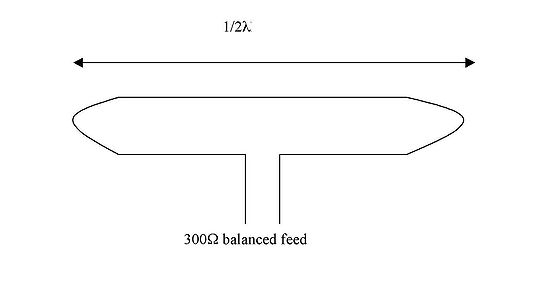
Folded dipoles are also 1/2 wavelength long. (The Greek letter <math>\lambda</math> is commonly used to represent wavelength.) However, the radiating elements are made of two parallel wires that are connected at the ends, and the feed point is at the center of one of the two wires.
The advantage of the folded dipole is that its impedance is about 300 ohms, allowing it to be fed with a 300-ohm balanced line. It is possible to make both the radiating elements and the feedline from 300-ohm twin-lead, although some type of antenna tuner or matching section will be required to transform the impedance to 50 ohms at the transceiver.
These antennas are commonly used on FM repeaters on VHF bands, although care should be taken using 300-ohm twin-lead at VHF and higher frequencies.
Another advantage of a folded dipole is that it has a wide usable bandwidth, allowing it to cover more of the band. However, folded dipoles cannot be used as part of a fan dipole, and unlike conventional single-wire dipoles, they cannot be used on their even harmonics – they are resonant on odd harmonics. (Both of these limitations occur because conventional dipoles have higher impedance away from their resonant frequencies and reach minimum impedance at resonance, while folded dipoles have lower impedance away from resonance and approach maximum impedance at resonance. At DC, a folded dipole is a direct short across the feed point, while a conventional dipole is an open circuit.)
Fan Dipole
Several dipoles with different lengths, each of which is resonant on a different band, can be connected together at a common feed point and fed with a single feedline. This is known as a fan dipole. The radiating elements of the dipoles should not run parallel to each other.
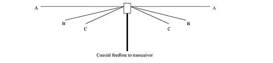
Each of the dipole element pairs A, B and C in this diagram would usually be cut for a frequency in the center of the required amateur band. The total length of each dipole pair is 1/2<math>\lambda</math>.
Approximate total lengths of dipole elements
| Amateur band | total length (feet) | total length (meters) |
| 80 meters sband | 120 feet | 37 meters |
| 40 meters band | 66 feet | 20 meters |
| 20 meters band | 33 feet | 10.2 meters |
| 10 meters band | 16.5 feet | 5.0 meters |
Coaxial Dipole (Double Bazooka)
The coaxial dipole antenna consists of a half-wavelength section of coax line with the shield opened a center and feed line attached to the open ends of the shield. The outside conductor of the coax acts as a half-wave dipole in combination with the open wire end sections of the antenna.
The inside sections, do not radiate but act as quarter-wave shorted stubs which presents a high resistive impedance to the feed point at resonance and tends to cancel reactance as frequency off resonant frequencies, thus increasing bandwidth.
The antenna can be cut for any operating frequency, from 160-meters down. The RG-58U is capable of handling a full kilowatt.
This design is broad-banded will provided low SWR over the entire 80 and 40-meter bands. Construction techniques are not critical. It can be put together with insulators and relief strains or thrown together in an emergency with just twisting and taping. How well it’s built will determine how long it stays up of course.
The coaxial dipole antenna is perfect for stealth work. As it is insulated it can be placed in trees, under eaves or next to house trim even in attics. It can be put up as a dipole, inverted V, vertical dipole and sloper. Its ends can be bent to accommodate unusual spaces. The 40-meter antenna can be used for 15 meters.

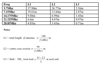
Dimensions guide
Coaxial Trap Dipole
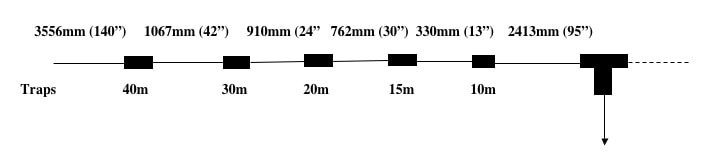
The Coaxial Trap Dipole is an asymmetrical wire antenna with traps at various points along the dipole arms to make them resonant at the required frequencies.
The diagram below shows approximate positions for coaxial traps. These should be verified by cutting them longer and trimming to achieve resonance.
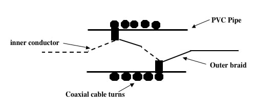
Coaxial traps
Coaxial traps are coils of coaxial cable wound around cylindrical formers as shown in the diagram below. Please note the connection details inside the former.
Formers can be strengthened in a number of ways to avoid stress on the solder joints:
- making a wire “handle” passing through each and of the former. Solder the internal wiring to the handle where it passes through the end of the former, and the “dipole wire” to the other end of the handle.
- Passing a wood, plastic, fiberglass rod through the former. Use this to provide support for the solder joints.
- The traps can be waterproofed by filling them with silicon sealers.
Trap dimensions and frequencies
Other Dipole Variants
- “Rabbit ears” dipoles are commonly used for TV reception. The position and length of the dipole arms can be adjusted to optimise reception.
- A bowtie antenna is a dipole element in which each section of the driven element is narrow at the feed point and widens at the ends. As this yields a slightly wider bandwidth for the antenna, bowties are commonly used as driven elements on panel antennas for wideband UHF broadcast reception.
- A loaded or shortened dipole may be constructed using inductive loading coils in each half of the dipole. Like loading coils for vertical antennas, these may be installed at the feed point or (preferably) in the center of each element section. As a dipole consists of two quarter-wave segments (instead of the single quarter-wave element of a vertical), two loading coils are required.
- A fan dipole (above) consists of multiple dipoles, each cut to a different length for a different band and spaced a few inches from each other. All of the individual dipole elements in the fan dipole share a common feed point. This design may be combined with the shortened dipole by providing loading coil pairs for each individual band. As these antennas can cover multiple bands (such as 20m, 40m, 80m) using one relatively simple design, these are popular for portable radio-amateur operations such as Field Day.
- Many of the most common complex antenna designs, such as yagi antennas, log-periodic, panel antennas or corner reflector antennas, are based on one or more dipoles as driven elements, supplemented by added reflectors or directors to add directionality and gain.
Remarkable! Its really awesome post, I have got much clear idea regarding from this piece
of writing.
Vi faccio i miei complimenti. Sono molto soddisfatto delle vostre spiegazioni tecniche facile da apprendere e sempre professionale!!