What Is Capacitors?
A capacitor, also known as a condenser, is a device that stores energy in an electrical field. Capacitors are open circuits to DC current, but their impedance drops as AC current passing through them has its frequency increased. Extremely high-frequency currents see capacitors as short circuits.
In some ways, capacitors behave as the opposite of inductors. This property is critically important to the circuit design of oscillators.
Fundamentally, capacitors consist of two conducting plates separated by an insulating material. The insulating material is known as the dielectric.
Dielectric materials commonly used in capacitors include air, glass, ceramic, paper, polycarbonate, and polyester.
What Is Capacitance?
Capacitance (C) is a measure of the amount of electric charge (Q) stored on each plate of a capacitor for a given voltage (V) across the plates:
- <math>C = {Q \over V}</math>
A capacitor has a capacitance of one farad (F) if one coulomb (C) of charge is stored when one volt (V) is applied across the plates. The farad is a very large unit, so values of capacitors are usually expressed in microfarads (µF), nanofarads (nF), or picofarads (pF).
Capacitance is proportional to the surface area of the conducting plate and inversely proportional to the distance between the plates. It is also proportional to the permittivity of the dielectric (that is, the non-conducting substance that separates the plates.
Capacitive Reactance
The impedance of a capacitor is given by the formula
- <math>Z = {1 \over j\omega C}</math>
Where <math>C</math> is the capacitance, <math>\omega</math> is <math>2 \pi f</math>, and <math>f</math> is the frequency. <math>j</math> is “operator j” from phasor analysis.
In practical terms this leads to:
<math> X_c = \frac {1} {2\pi F C} </math> where
- <math> X_c </math> is capacitive reactacnce
- F is the frequency of operation in Hertz
- C id the capacitance in Farads
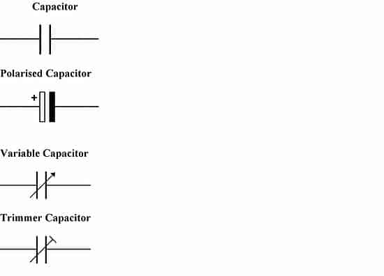
Capacitor circuit symbols
Capacitors in series and parallel
Parallel
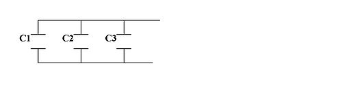
Capacitors in a parallel configuration each have the same potential difference (voltage). Their total capacitance (CT) is given by:
- <math> C_{T} = C_1 + C_2 + C_3 \,</math>
The reason for putting capacitors in parallel is to increase the total amount of charge stored by increasing the capacitance.
Series

The current through capacitors in series stays the same, but the voltage across each capacitor can be different. The sum of the potential differences (voltage) is equal to the total voltage. Their total capacitance is given by:
- <math> \frac{1}{C_{T}} = \frac{1}{C_1} + \frac{1}{C_2} + \frac{1}{C_3}</math>
When in series, the distance between the plates has effectively been increased, reducing the overall capacitance. In practice, capacitors will be placed in series as a means of economically obtaining very high voltage capacitors, for example for smoothing ripples in a high voltage power supply.
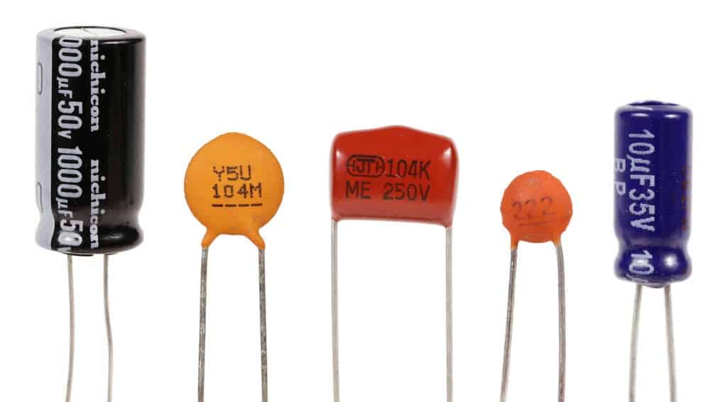
Capacitor values and Identification
Capacitor markings
Most capacitors have numbers printed on their bodies to indicate their electrical characteristics.
Some are indicated with XYZ K/M VOLTS V where XYZ stands for the capacitance, the letters K or M indicate the tolerance of ±10% or ±20% respectively and VOLTS V represents the working voltage.
Example:
A capacitor that has written on its body:
105 K 330 V
is a capacitor 10 x 10^5 pF ± 10% with a working voltage of 330 V
A capacitor
103 M 100 V
is a capacitor 10 x 10³ pF ± 20% with a working voltage of 100 V, or 10,000 x 10-12 farad, or 0.01 µF (microfarad).
The rule is: x 10Z pF (picofarads) tolerance work voltage
Standard values
In the early days of electronics, components were often made to fit a specific need, the values of early capacitors were of arbitrary (usually integer) base numbers. The more common values included 1.0, 1.5, 2.0, 3.0, 5.0, 6.0, and 8.0 as base numbers, but they were not necessarily limited to these values. Values were generally in microfarads (µF) and could be multiplied by any power of ten; picofarads were often called micro-microfarads (µµF) then.
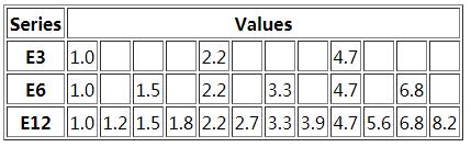
In the late 1960s, a standardized set of geometrically increasing base values was introduced. According to the number of values per decade, these were called the E3, E6 or E12 series:
The same series are used for resistors, where E24/E48/E96 series are additionally used for even lower-tolerance components. These number series are known as preferred values.
Since most electrolytic capacitors have a tolerance range of ±20%, meaning that the manufacturer is stating that the actual value of the capacitor lies within ±20% of its nominal value, they are normally available in E6 (or even just E3) series values only (e.g. 2200 µF, 3300 µF, 4700 µF) – the tolerance ranges overlap the intermediate values from the next higher series anyway.
Other types of capacitors, e.g. ceramic, can be manufactured to tighter tolerances and are available in E12 values (e.g. 47 pF, 56 pF, 68 pF).
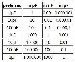
Capacitors were once specified by their values in either microfarads or picofarads, which meant that both very small (such as 0.01 µF) and very large (such as 10,000 pF) numbers were in common use. Nowadays, it is considered preferable to use the nanofarad as well, and specify all values in the numeric range 1 – 999 only;
this makes the examples given above equal to 10 nF (yes, they are both the same!). Above 999 µF, the practice is not yet in common use; capacitors are not usually specified in millifarads (mF), probably because it would be too easily confused with microfarads (for which mF was once an acceptable abbreviation).
A table giving translations of previous commonly used multiples is as follows:
Colour coding
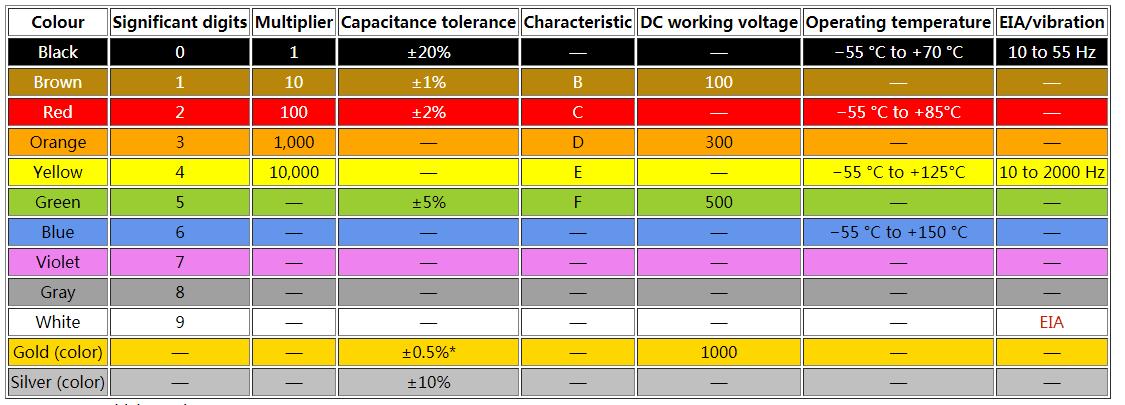
*Or ±0.5 pF, whichever is greater.
Capacitor types
Fixed capacitor comparisons
| Capacitor type | Dielectric used | Features/applications | Disadvantages |
|---|---|---|---|
| Paper Capacitors | Paper or oil-impregnated paper | The impregnated paper was extensively used for older capacitors, using wax, oil, or epoxy as an impregnant. Oil-Kraft paper capacitors are still used in certain high voltage applications. Has mostly been replaced by plastic film capacitors. |
Large size. Also, paper is highly hygroscopic, absorbing moisture from the atmosphere despite plastic enclosures and impregnates. Absorbed moisture degrades performance by increasing dielectric losses and decreasing insulation resistance. |
| Metalized Paper Capacitors | Paper | Comparatively smaller in size than paper-foil capacitors | Suitable only for lower current applications. Has been largely superseded by metalized film capacitors |
| PET film or Mylar film Capacitor | Polyester film | Smaller in size when compared to paper or polypropylene capacitors of comparable specifications. May use plates of foil, metalized film, or a combination. Mylar capacitors have almost completely replaced paper capacitors for most direct current electronic applications. Operating voltages up to 60,000VDC and operating temperatures up to 125°C. Low moisture absorption. | Temperature stability is poorer than paper capacitors. Usable at low alternating current frequencies, but inappropriate for radio frequency applications due to excessive dielectric heating. |
| Kapton Capacitor | Kapton polyimide film | Similar to PET film, but significantly higher operating temperature (up to 250°C). | Higher cost than PET. Temperature stability is poorer than paper capacitors. Usable at low AC frequencies, but inappropriate for RF applications due to excessive dielectric heating. |
| Polystyrene Capacitor | Polystyrene | Excellent general purpose plastic film capacitor. Excellent stability, low moisture pick-up and a slightly negative temperature coefficient that can be used to match the positive temperature co-efficient of other components. Ideal for low power RF and precision analog applications | Maximum operating temperature is limited to about +85°C. Comparatively bigger in size. |
| Polycarbonate Plastic Film Capacitor | Polycarbonate | Superior electrical insulation electrical resistance, dissipation factor, and dielectric absorption compared to polystyrene capacitors. Moisture pick-up is less, with about +/- 80 ppm temperature co-efficient. Can use full operating voltage across entire temperature range (-55°C to 125°C) | Maximum operating temperature limited to about 125°C. |
| Polypropylene Plastic Film Capacitors | Polypropylene | Has become the most popular capacitor dielectric. Extremely low dissipation factor, higher dielectric strength than polycarbonate and polyester films, low moisture absorption, and high insulation resistance. May use plates of foil, metalized film, or a combination. Film is compatible with self-healing technology to improve reliability. Usable in high frequency applications due to very low dielectric losses. Larger value and higher voltage types from 1 to 100μF at up to 440V AC are used as run capacitors in some types of single phase electric motors. | More susceptible to damage from transient over-voltages or voltage reversals than oil-impregnated Kraft paper for pulsed power energy discharge applications. |
| Polysulphone Plastic Film Capacitors | Polysulfone | Similar to polycarbonate. Can withstand full voltage at comparatively higher temperatures. Moisture pick-up is typically 0.2%, limiting its stability. | Very limited availability and higher cost |
| PTFE Fluorocarbon (teflon) Film Capacitors | Polytetrafluoroethylene | Lowest loss solid dielectric. Operating temperatures up to 250°C, extremely high insulation resistance, and good stability. Used in stringent, mission-critical applications | Large size (due to low dielectric constant), and higher cost than other film capacitors. |
| Polyamide Plastic Film Capacitors | Polyamide | Operating temperatures of up to 200°C. High insulation resistance, good stability and low dissipation factor. | Large size and high cost. |
| Metalized Plastic Film Capacitors | Polyester or Polycarbonate | Reliable and significantly smaller in size. Thin metalization can be used to advantage by making capacitors “self healing”. | Thin plates limit maximum current carrying capability. |
| Stacked Plate Mica Capacitors | Mica | Advantages of mica capacitors arise from the fact that the dielectric material (mica) is inert. It does not change physically or chemically with age and it has good temperature stability. Very resistant to corona discharge damage | Unless properly sealed, susceptible to moisture pick-up which will increase the power factor and decrease insulation resistance. Higher cost due to scarcity of high grade dielectric material and manually-intensive assembly. |
| Metalized Mica or Silver Mica Capacitors | Mica | Silver mica capacitors have the above mentioned advantages. In addition, they have much reduced moisture infiltration. | Higher cost |
| Glass Capacitors | Glass | Similar to Silver mica capacitor. Stability and frequency characteristics are better than silver mica capacitors. Ultra-reliable, ultra-stable, and resistant to nuclear radiation. | High cost. |
| Class-I Temperature Compensating Type Ceramic Capacitors | Mixture of complex Titanate compounds | Low cost and small size, excellent high frequency characteristics and good reliability. Predictable linear capacitance change with operating temperature. Available in voltages up to 15,000 volts | Capacitance changes with change in applied voltage, with frequency and with aging effects. |
| Class-II High dielectric strength Type Ceramic Capacitors | Barium titanate based dielectrics | Smaller than Class-I type due to higher dielectric strength of ceramics used. Available in voltages up to 50,000 volts. | Not as stable as Class-I type with respect to temperature, and capacitance changes significantly with applied voltage. |
| Aluminum Electrolytic Capacitors | Aluminum oxide | Very large capacitance to volume ratio, inexpensive, polarized. Primary applications are as smoothing and reservoir capacitors in power supplies. | Dielectric leakage is high, large internal resistance and inductance limits high frequency performance, poor low temperature stability and loose tolerances. May vent or burst open when Electrically overloaded]] and/or overheated. Limited to about 500 volts. |
| Tantalum Electrolytic Capacitors | Tantalum pentoxide | Large capacitance to volume ratio, smaller size, good stability, wide operating temperature range, long reliable operating life. Extensively used in miniaturized equipment and computers. Available in both polarized and unpolarized varieties. Solid tantalum capacitors have much better characteristics than their wet counterparts. | Higher cost than aluminum electrolytic capacitors. Voltage limited to about 50 volts. Explodes quite violently when voltage rating, current rating, or slew rates are exceeded, or when a polarized version is subjected to reverse voltage. |
| Electrolytic double-layer capacitors (EDLC) Supercapacitors | Thin Electrolyte layer and Activated Carbon | Extremely large capacitance to volume ratio, small size, low ESR. Available in hundreds, or thousands, of farads. A relatively new capacitor technology. Often used to temporarily provide power to equipment during battery replacement. Can rapidly absorb and deliver larger currents than batteries during charging and discharging, making them valuable for hybrid vehicles. Polarized, low operating voltage (volts per capacitor cell). Groups of cells are stacked to provide higher overall operating voltage. | Relatively high cost. |
| Alternating current oil-filled Capacitors | Oil-impregnated paper | Usually PET or polypropylene film dielectric. Primarily designed to provide very large capacitance for industrial AC applications to withstand large currents and high peak voltages at power line frequencies. The applications include AC motor starting and running, phase splitting, power factor correction, voltage regulation, control equipment, etc.. | Limited to low frequency applications due to high dielectric losses at higher frequencies. |
| Direct current oil-filled capacitors | Paper or Paper-polyester film combination | filtering, bypassing, coupling, electric arc|arc suppression, voltage doubling, etc… | Operating voltage rating must be derated as per the curve supplied by the manufacturer if the DC contains ripple. Physically larger than polymer dielectric counterparts. |
| Energy Storage Capacitors | Kraft capacitor paper impregnated with electrical grade castor oil or similar high dielectric constant fluid, with extended foil plates | Designed specifically for intermittent duty, high current discharge applications. More tolerant of voltage reversal than many polymer dielectrics. Typical applications include pulsed power, electromagnetic forming, pulsed lasers, Marx generators, and pulsed welders. | Physically large and heavy. Significantly lower energy density than polymer dielectric systems. Not self-healing. Device may fail catastrophically due to high stored energy. |
| Vacuum Capacitors | Vacuum capacitors use highly evacuated glass or ceramic chamber with concentric cylindrical electrodes. | Extremely low loss. Used for high voltage high power RF applications, such as transmitters and induction heating where even a small amount of dielectric loss would cause excessive heating. Can be self-healing if arc-over current is limited. | Very high cost, fragile, physically large, and relatively low capacitance. |