Are Compact Fluorescent Lamps (CFL’S) RF Quiet?
There has been a lot of exchanging of views about these lamps in the press of late and it revolves around the light output and the initial purchase price and are they worth the expense.
I will leave this subject to others to thrash out.
In this review, I will present my personal findings during a range of experiments I conducted.
I wanted to see if the CFL would add any background hash to the amateur radio bands and in general to short wave and broadcast bands.
For my test setup, I used the following.
1 x 500 Mhz RF Spectrum Analyser
1 x Sony portable three-band portable radio
1 x Kenwood R600 Communications Receiver
1 x Telescopic whip antenna for the input to the spectrum analyzer
1 x Philips GENIE 14 watt CFL (Cool Daylight) model
Test arrangement
The Genie Lamp was mounted on the workbench and the spectrum analyzer was located 1 meter away with the Telescopic whip fitted to the input.
The Sony portable radio and the Kenwood R600 were 1 Mtr distance from the lamp. Short 3 Mtr wire antennas were used.
Obtain a baseline
The spectrum analyzer was set up and a baseline reading was taken in the shack on background noise floor levels.
Test Number 1
The analyzer was tuned across the RF spectrum between 200Khz and 500Mhz and the CFL turned on and off to see if any response was found.
Result
The CFL radiated an RF energy pulse that was broadband in nature and lasting for a period of 1.5 seconds at each switch-on period. The pulse was up to 5 Mhz in width and at random intervals from 200Khz to 95 Mhz. The intensity was in the order of 15 DB from the baseline floor reading
Monitoring the noise on the Sony portable radio on Broadcast AM band produced what sounded like 100Hz power supply buzz that blocked out completely all radio stations outside the local reception area. The Radio station in Kempsey on 531 Khz was completely swamped.
Following the 1.5-second start-up period, the broadcast band was left with a background buzz of the same type but slightly lower intensity. The reading on the analyzer was in the order of 3 dB off the baseline.
Test Number 2
The lamp was turned on and off and it was noted that a permanent rise in background RF noise with the lamp on was centered on 41 MHZ. The rise has spread either side of this out to plus and minus 5 MHZ. The peak was 6 DB above the noise floor.
Another significant rise was centered on 3.1Mhz in the same magnitude.
Test Number 3
Using the Kenwood R600 the same results were confirmed on the broadcast band and on 3.1MHZ the 100 Hz buzz was very noticeable. Signal strength on the S meter indicated S7.
Conclusion.
CFL’s are not RF quiet and despite having the “C” tick and electrical authority approval they do indeed radiate RF energy.
Remember that for this test I used a well-known brand, it makes you wonder about the other less well know types that how they would perform in these and other tests.
Also, remember that some households possibly your neighbors have dozens of these lamps installed, that is a lot of RF been radiated
Personal Observations
I have used one of these lamps in my shack for a period of one (1) month and have removed it. The light output despite all the claims is not the same as a 75-watt light globe and they also contain phosphor and mercury along with the inverter circuit contained inside the base of the lamp. They cost at the very best 3 times that of a quality incandescent globe and I am sure that the carbon footprint to make them is a lot larger.
I have seen Hams use these devices in Magi Lamps. If you are fault-finding a circuit how much RF hash are you introducing into the circuit under test and possible into your test equipment as well?
I am also reliably informed that the New Zealand Government has reversed a decision to ban the humble incandescent light bulb in recent weeks.
A High Accuracy Method Of Logging Noise Occurrences
by Alan Robinson, W4LKE
In view of the fact that other hams might want to use my method of recording noise, I think I should give you some more details about how I do it.
Equipment used: Icom 756PRO Receiver with Astron RS-35M Power Supply, Icom PW1 Amplifier, G5RV antenna, Radio Shack Model 22-805 Digital Multimeter, and a PC compatible computer running Windows 98 SE.
The PW1 is used, in this case, only as an antenna tuner. The Radio Shack 22-805 is connected to one of my serial ports.
I have an 8-ohm non-inductive resistor plugged into the external speaker jack to replace my external speaker. The multimeter is set to measure the voltage, in millivolts, across this resistor. Actually one can just connect the multimeter across a jack plugged into the external speaker jack, but I prefer to have the resistor replace the speaker.
Equipment settings: I use the ScopeView feature of the Radio Shack software, not the logging feature. The ScopeView software has exactly all the features I need.
The Icom 756PRO is set on AM with the AGC set to off. This is very important. The AGC of the audio output voltage, in millivolts, across the 8-ohm resistor is directly proportional to the voltage, in microvolts, at the antenna jack of the 756PRO. This does disable the S meter.
I set the receiver to 29.291 MHz. This was determined by doing a sweep from 1.8 MHz to 50 MHZ to see where the noise was the loudest. I got strong signals at many places across this frequency range but decided that the 10-meter band would be a good place to record the noise.
It is also important to pick a frequency NOT often used by hams. If a station comes on the frequency you are monitoring the data is of no value. I have found that there is very little activity at 29.291 MHz.
The 756PRO also has a spectrum scope that I set to +/- 100 kHz to see if there are close-by signals that might contaminate my data.
The voltages recorded are, of course, dependent on the audio level. I set the volume control to produce 5 mV with no antenna connected. With that setting and a very quiet noise level, the voltage level is about 10 to 12 mV with the antenna connected. An S9 noise signal reads about 200 mV.
I set the ScopeView software to 40 mV per division (this gives a maximum of 320mV). I use the 1-minute sampling rate and repetitive sweep. This will give three screens in a 24 hour period. This can be mounted on one 8 1/2 x 11 sheet of paper. Each day I stop recording and print the “scope” screens.
Actually, when the 1-minute sample rate is used it is really a recording rate. The Radio Shack multimeter samples at 1 second. So, if a peak noise occurs somewhere during the 1-minute recording, the peak will also be recorded and show on the right side of the ScopeView screen.
I have also made a number of “calibration” runs. I set the sample rate of ScopeView to 1 second. Then, when the noise level is high, I momentarily turn the AGC on to get the S meter reading. Then turn the AGC off again and let ScopeView record for 30 seconds. This is one large division in ScopeView. Next, I turn on 6 dB of attenuation in the 756PRO. Turn the AGC on to get the new S meter reading. Then turn the AGC off and collect data for another 30 seconds. This is repeated with 12 and 18 dB of attenuation. Note: the S meter on my receiver is NOT calibrated to 1 S unit for 6 dB.
When I show the data to the utility I also give them the calibration plots so that the millivolt reading corresponds to S meter noise levels. Everyone agrees that S9, or especially 20 dB over S9, is not acceptable and must be fixed.
Results from the recording system: I have recorded the noise at various times over the last four months. Recently I have been recording it continuously. During times when the utility has been working on the lines, I have used the 1-second sampling rate in ScopeView.
On one occasion the utility shut down the 69 kV transmission that runs 100 feet North of our house. I and another ham were recording the noise. The instant that the voltage was dropped from the line our noise dropped from S7 to S1. The recording system showed the exact times that the 69kV was off. Very convincing evidence!!
On another occasion, the utility opened a cutout on the underbuilt 7.5kV distribution line. Again I used the 1-second sample rate in ScopeView. The noise quit when this cutout was opened. The lineman then cycled the cutout several times. The data showed the exact times for each cycling of the cutout as it was opened and closed. Again very convincing! The cutout was replaced.
OK. So why are we still working on it? Well, we haven’t found all the sources yet. I have been using Marv Loftness’s method and have identified poles that are sparking. I have recorded their sparking patterns and printed them out.
During one particularly noisy time, I recorded the sparking pattern at my station on 52 MHz. Then I went to the “problem pole” and recorded the same sparking pattern from that pole on 440 MHz with a six-element beam. I gave copies of these plots to the utility. Again very convincing!
I also prepared a map of the power line in our area with all the poles identified. I used a GPS receiver to get the pole positions. Also, I obtained the position of W7PUA’s 2-meter antenna. During several noise measurements Bob Larkin, W7PUA, used his highly directional array to take bearings toward the high noise area. I then plotted those on the same map. The bearing toward the greatest noise pointed directly at the problem pole in the previous paragraph. The map was presented to the utility.
In all, I gave the utility data covering nearly three continuous weeks and selected data before that, including the time they shut down the 69 kV line. I also gave them calibration curves, maps with bearing and pole positions, pictures of my spectrum scope, the audio recording of the noise during S9 conditions, and the scope pictures of the sparking patterns.
Summary: I used this method for about four months now, refining it as I go along. Lately, I have been leaving the system on all the time and getting 24/7 recordings. Two days ago I gave the utility 2 1/2 weeks of continuous plots, with calibration curves. There is no doubt as to when the noise is “on” and when it is not. In our case, hard rain wipes out the noise.
Comment: The utility knows the interference is their power lines. They are now in the process of making a plan to cure it.
I hope this helps other hams. If I can be of any assistance please let me know. Email is best, but the phone is OK too.
Sincerely, and 73s,
Alan, W4LKE
Alan Robinson – Corvallis, OR
Cure for RFI from “invisible” dog fence
By Phil K7UF
– Get two Radio Shack (Catalog #: 273-104)toroids
– wind them with 22 gauge wire at least 20 times on each toroid I have 24 turns on each of mine
– do this on each of the two toroids then place one each in series with the fence antenna at the transmitter.
My noise level went from s9 on 80 meters to nothing no noise from the dog fence. The toroids from the Shack are good for hf from 1500 kHz to 30 mhz…below 1mhz it rolls down to zero. Below 100 kHz its zero attenuation which allows the dog fence transmitter to work as it normally does with no ill effects. Most of these dog fences operate in the 7khz to 15khz region.
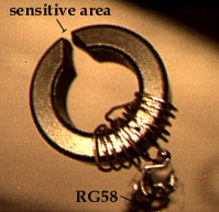
Simple RFI sniffer from WA2ISE
To track down exactly where RFI is coming out of a computer or other equipment, use this RFI sniffer. It’s a ferrite toroid ring with a gap cut into it. Several turns of wire connect to coax that then feeds into a receiver or spectrum analyzer (I’m sure you have one handy!). The gap is the sensitive area. It will pick up RFI magnetic fields. Thus you can identify wires or other leakage areas with RFI on them.
It takes a long time to fill the gap into the toroid; your needle files will get dull. Don’t push too hard, as ferrite is fragile. You want a narrow gap on the outside part of the ring, so file from the inside. A gap about the thickness of a fingernail is good. Depending on the ferrite material, this sniffer should be good for HF and VHF.
For low-frequency work, use a tape head from an audio cassette machine. The center of the front part of the head (where the tape used to pass over) will be the sensitive spot.
There is a commercial AM radio tower within 4 miles of my receiver. I am picking up their signal and harmonics on various frequencies. Short of moving, is there anything that can be done, filters?
Thanks