The VHF Quagi from an article by Wayne Overbeck, K6YNB in QST April 1977; “Building a 440MHz Quagi” description is from Gary Bonnor – VK4ZGB
There have been many half-hearted attempts to combine a Yagi and a Quad. Most have produced questionable results. Well, here are the “true” facts, the real dope, the hot scoop.
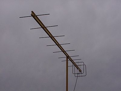
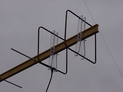
As its name suggests, the quagi combines the best features of the cubical quad and the linear Yagi-Uda beam antenna. This article describes an eight element quagi design with quad type driven element1 and reflector plus six Yagi type parasitic directors.
The result is an antenna that has outperformed all similar size conventional Yagis and a number of bigger ones at three VHF conferences where antenna gains were measured. At frequencies above 144 MHz, only larger and very well tuned antennas tend to outperform the eight element Quagi. But equally important, the quagi can be built by the average amateur with simple materials at a fraction of the cost of a commercial antenna.
The Quagi requires neither fine tuning nor careful handling. Many of these antennas have survived several years of bouncing up and down mountain roads that are little more than goat trails. The elements can be bent and straightened without affecting the gain or VSWR.
The antenna’s secret, if there is one, is its hybrid character. With Yagi type directors, the quagi retains the simplicity and gain of a long boom Yagi without the Yagi drawback at VHF – a dipole driven element. As many antenna builders have learned, matching a Yagi at VHF (and especially at UHF) is not easy.
Gamma matches tend to become less than effective at these frequencies, and other feed methods such as the delta with a balun and universal stub lead to cumbersome antennas that may not endure rough handling or wet weather.
In fact, some of the best VHF-UHF antennas these days, both homemade and commercial, are hybrid designs that avoid the problems inherent in a Yagi type dipole driven element by not using one!
Notable commercial examples of this trend are the log-periodic Yagi (using a log-periodic type broadband feed) and a 20 element colinear with yagi type directors. Both are effective antennas, sans dipole feed problems.
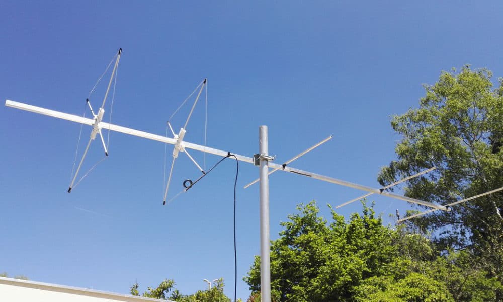
The Quagi solves the feed problem in a way that is more practical for the amateur by using a quad type driven element that requires no tuning at all for good performance, even at 432 MHz. The Quagi can be fed directly with RG-8/U (or if necessary, RG-11/U, since the characteristic impedance of the loop is about 60 ohms at resonance).
Anyone who can measure off some lengths of wire can build one and make it work, with no test equipment at all. The quad loops don’t even have to be very “square” for the antenna to work correctly. Besides the simplicity, the quad loops offer a fringe benefit of a little extra gain over linear half-wavelength elements. More about that in a moment.
Some Quad – Yagi Theory
Although this is a practical construction article and not a theoretical treatise on antenna design, it would violate the spirit of amateur radio to merely present the dimensions and send people racing off to build a new type of antenna without any discussion of its theoretical basis.
The Yagi-Uda antenna with its half-wavelength linear elements was very popular before amateurs began experimenting with parasitic beams made of full-wavelength wire loops. However, it became apparent in the 1940’s and 1950’s that the cubical quad rivaled the performance of a conventional Yagi.
An excellent history and theoretical explanation of the quad appears in Orr’s “Quad Antennas”1. In fact, Orr provided some of the inspiration for the quagi when he suggested that a two-element quad had an edge over a two-element Yagi because of the loop gain (perhaps an extra 1.5 dB). However, he found that quads seemed to lose this advantage as more elements were added.
Others have disputed that conclusion, notably Bergen2, Lindsay3 and more recently Harrison4. Lindsay’s studies at the Denver University antenna range in the 1960s suggested that, for any given boom length, a quad would outperform a Yagi by about 2 dB. Harrison summarized two scholarly antenna studies and concluded that a loop-Yagi (i.e., a quad type antenna) with any number of elements probably outperforms a similar size Yagi by 1 dB or more.
Lindsay reported that a Yagi must have nearly twice the boom length of a quad to achieve the same gain. This author took advantage of the high gain per foot of boom of the quad to build and extremely compact and lightweight moonbounce array of 16 three-element quads for a recent 2-meter DXpedition to Alaska. A description of this small high-gain antenna appears in a moonbounce application note published by Eimac5. The Alaskan moonbounce expedition itself was recently described in QST6.
The Birth of the Quagi
This type of thinking led to the inspiration for the quagi. More immediately, though, the quagi was born because a commercial Yagi for 432 MHz performed poorly. It’s a story worth reading if you have ever believed the exaggerated catalog gain figures for some commercial antennas.
In 1970, I took a brand-new commercial Yagi which had a claimed gain figure of 13.5 dBd to a measuring session at the West Coast VHF Conference. It measured 6.4 dB over a dipole! A quick check revealed no errors in assembly, and an identical Yagi was soon measured – also around 6 dB gain!
“It’s a gamma match. They don’t work at 432 MHz,” a veteran of many VHF antenna measuring sessions said knowingly. “In fact, few amateurs can put together any kind of feed system that works well at that frequency,” he added.
That was a bit of an overstatement, of course. Several true Yagi designs have now been published that work well at 432 MHz – including the W1HDQ classic “Tilton Yagi, “7 and newer designs by Knadle8 and Hilliard9. However, all three use matching systems that require considerable skill to tune. Having read what Orr, Lindsay and others have said about quads and Yagis, the author wondered if a quad type of feed might be the answer.
Before the next West Coast VHF Conference, the ill-performing, store-bought Yagi was modified in only one way. the driven element was removed and replaced with a quad type loop of no. 12 wire. There was no matching of any kind. A type-N connector was soldered in the center of the quad loop bottom side, and it was fed directly with RG-8/U.
Now the SWR and gain both looked better. In the gain contest at the next VHF Conference, this antenna was measured at 9.8 dB over a dipole. Simply eliminating the gamma-matched dipole and adding a quad loop had increased the gain 3.4 dB!!!
That led WB6RIV and the author into a summer of antenna design work on a backyard antenna range with a signal source, a remote dipole and a field-strength meter. If just replacing the driven element would get us an extra 3.4 dB, what could be done with a whole new design optimized for a mix of quad and Yagi type elements?
Many, many antennas later, we had an eight-element quagi whose element lengths and spacing seemed about right, with an overall antenna size that seemed to be a good compromise between bulk and gain.
The rest is history. The quagi has won three consecutive 2-meter antenna-gain contests at West Coast VHF Conferences with measured gains up to 14.2 dB over a dipole10. The 220-MHz version has won two out of three measurements (losing once to a much bigger log-periodic Yagi).
Even on 432 MHz, where the quagi with its four-foot 10-inch (1.47M) boom is usually one of the smallest parasitic antennas measured, it finishes high in the standings, not far behind the 10-foot (3.0M) Yagis.
In presenting this information, the author does not mean to imply that the 2-meter version of the eight-element quagi will outperform some of the largest antennas, such as the popular 16-element collinear.
Both are a bit big to enter in gain contests, but bother probably outperform the quagi by 1.5 to 2.0 dB on 144 MHz. On 432 MHz a 12-foot (3.66M) log-periodic Yagi described by Holladay11 and made commercially by KLM Electronics tops the four-foot 10-inch (1.47M) quagi by about 2.8 dB. (But it costs and weighs at least 6 dB more!!!!)
New Ideas, Anyone?
As far as we know, no quagi of any size has ever been built for a frequency below 144 MHz. A 20-meter quagi would probably be a very good antenna, but it would be 140 feet (42.6M) long!!! Moreover, gamma-matched dipoles work well at 14 MHz; this design was created to solve problems unique to the VHF-UHF world.
A conventional Yagi may well deliver more gain per pound or per square foot of wind load at 20 meters. Even at 50 MHz, a quagi of this design would be too big for the author’s portable expeditions and contest work.
If what you want is a good, easy-to-build antenna for 144, 220, or 432 MHz, the quagi may be your answer. Here are the construction details.
How to Build a Quagi
There are few tricks to quagi building. The author has mass produced as many as 16 in one day. Table 1 gives the dimensions for various frequencies.
The boom is wood or any other nonconductor (e.g., fiberglass). If you use a metal boom, you’ll have to redesign the whole thing and come up with new element lengths. Many VHF antenna builders go wrong by failing to follow this rule: If the original uses a metal boom, use the same size and shape metal boom when you duplicate it.
If it calls for a wood boom, use a nonconductor. Many amateurs dislike wood booms, but in the author’s salt-air environment they outlast aluminum, ( and surely cost less). Varnish the boom if you wish.
The 2-meter version is usually built on a 14 foot (4.27M) 1″ (25mm) x 3″ (75mm) boom, with the boom cut down to taper it to one inch (25mm) at both ends. Clear pine is best because of its lightweight, but construction grade Douglas fir works well. At 220 MHz, the boom is under 10 feet (3.05M) long and most builders use 1 (25mm) x 2 (50mm) or (preferably) 3/4 (20mm) by 1-1/4 inch (30mm) pine molding stock. On 432 MHz the boom must be 1/2-inch (12mm) thick or less. Most builders use strips of 1/2-inch (12mm) exterior plywood for 43212.
| Element Lengths | 144.5 MHz | 147 MHz | 222 MHz | 432 MHz | 446 MHz |
|---|---|---|---|---|---|
| Reflector (all No 12 TW wire, closed) | 2200 mm loop | 2159 mm | 1432 mm | 711 mm | 689 mm |
| Driven Element (No 12 TW, fed at the bottom) | 2083 mm loop | 2032 mm | 1359 mm | 676 mm | 657 mm |
| Directors | 913 mm to 889 mm in 5 mm steps | 897 mm to 873 mm in 5 mm steps | 594 mm to 568 mm in 3 mm steps | 298 mm to 291 mm in 1.5 mm steps | 289 mm to 280 mm in 1.5 mm steps |
| Spacing | |||||
| R – DE | 533 mm | 521 mm | 346 mm | 178 mm | 173 mm |
| DE – D1 | 400 mm | 391 mm | 260 mm | 133 mm | 130 mm |
| D1 – D2 | 838 mm | 826 mm | 546 mm | 279 mm | 272 mm |
| D2 – D3 | 445 mm | 435 mm | 289 mm | 149 mm | 144 mm |
| D3 – D4 | 663 mm | 651 mm | 432 mm | 222 mm | 215 mm |
| D4 – D5 | 663 mm | 651 mm | 432 mm | 222 mm | 215 mm |
| D5 – D6 | 663 mm | 651 mm | 432 mm | 222 mm | 215 mm |
The quad elements are supported at the current maxima (the top and bottom, the latter beside the feed point) with Plexiglas or small strips of wood. The quad elements are made of no. 12 (2.8mm) copper wire, commonly used in house wiring. Some builders use no. 10 (3mm) wire on 144 MHz and no. 14 (2.5mm) wire on 432 MHz, although this changes the resonant frequency slightly. Solder a type-N connector (a SO-239 is often used at 2 meters) at the midpoint of the driven element bottom side, and close the reflector loop.
The directors are mounted through the boom. They can be made of almost any metal rod or wire about 1/8-inch (3mm) diameter. Welding rod or aluminum clothesline wire will work well if straight. The author uses 1/8-inch (3mm) stainless-steel rod secured from an aircraft surplus store.
A TV-type U-bolt mounts the antenna on a mast. The author uses a single machine screw, washers and nut to secure the spreaders to the boom so the antenna can be quickly “flattened” for travel. In permanent installations two screws are recommended.
Construction Reminders
Here are a couple of hints based on the experiences of those who have already built the quagi. first, remember that at 432 MHz even a 1/8-inch (3mm) measuring error will deteriorate performance. Cut the loops and elements carefully as possible. No precision tools are needed but be careful about accuracy. Also, make sure you get the elements in the right order. The longest director goes closest to the driven element.
Finally, remember that you are feeding a balanced antenna with an unbalanced line. Every balun the author has tried introduced more losses than the feed imbalance problem. Some builders have tightly coiled several turns of the feed line near the feed point to limit radiation further down the line. In any case, keep the feed line at right angles to the antenna. Run it from the driven element directly to the supporting mast and then up or down perpendicularly for best results.
Phasing Quagis
Like other antennas, quagis can be phased for additional gain. Arrays of two, four, eight, and sixteen have been phased successfully for tropospheric, meteor scatter and moonbounce work. Table 1 gives suggested stacking distances. When phasing quagis, make sure each bay is fed in the same sense. Each bay must have its driven element in the same relative position and must be fed with the center conductor going to the same side.
For those not wishing to calculate phasing-line lengths, here is a phasing plan for two quagis on 144 MHz that should achieve at least 2.5 dB stacking gain. Secure 25 feet (7.62M) of Belden no. 8224 feed line, an 80-ohm foam cable widely used in CATV applications, and mount PL-259 connectors (with UG-176 adaptors) on each end. Cut the cable into two 148-inch (3.76M) lengths, including the length of the connectors. You’ll have a few inches of cable left over. Strip the two open ends back 3/4-inch (20mm) and solder both outer braids into the grounded mounting holes on a SO-239 at the junction of the two phasing lines. If you use any other brand or type of coax than Belden no. 8221, the line lengths will probably be different.
Conclusion and Acknowledgement
The eight-element quagi has consistently performed well in many kinds of VHF-UHF service. It delivers high gain in an inexpensive and easy-to-reproduce design, even at 432 MHz. We hope this article will not only inspire others to build quagis, but also spend more time working DX on the exciting frequencies above 144 MHz.
The author wishes to thank Wilson Anderson, Jr., WB8RIV, for his valuable assistance in the development of the quagi antenna.
References
- Orr, Quad Antennas, 1st Ed., Wilton, CT. Radio Publications, Inc.
- Bergren, “The Multielement Quad,” QST, May 1963, Page 11.
- Lindsay, “Quads and Yagis,” QST, May 1968, Page 11
- Harrison, “Loop-Yagi Antennas,” Ham Radio, May 1976, Page 30
- The EIMAC moonbounce notes are available from Robert Sutherland, EIMAC Division of Varlan, 301 Industrial Way, San Carlos, CA 94070.
- Overbeck, “Moonbounce Boondoggle,” QST, February 1977.
- Tilton, “Yagi Arrays for 432 MHz,” QST April 1966, Page 19.
- Knadle’s 432 MHz Yagi is described in the ARRL Antenna Book, 13th Edition, (1974), beginning on page 243.
- Described in Smith, “The World above 50 MHz,” QST January 1972, Page 96.
- About measured gains in antenna gain contests: except on 432 MHz, where a National Bureau of Standards reference antenna is often used, the actual gain figure of a tested antenna means less than its relative performance compared to other antennas measured at the same time. On 144 and 220 MHz, there is rarely a reference antenna of known gain, so the actual gain figures may vary from one VHF conference to the next. One 144 MHz quagi received absolute gain figures ranging from 11.5 top 14.2 dBd at three measurements, winning each time with a different gain. Whatever its true gain, the merit of this quagi is best shown by its relative superiority to other antennas against which it has been measured.
- Holliday, “High Gain Yagi for 432 MHz,” Ham Radio, January 1976, Page 46.
- Note: The elements are intended to be mounted through the shorter dimension of the boom, Mounting the elements through the longer dimension of the boom may affect performance. Even vertically polarised quagis are normally assembled with the elements going through the shorter dimension, even if this means mounting the antenna “on its side” and supporting the boom with an outrigger line.
How to build a 440MHz Quagi?
This description is from Gary Bonnor – VK4ZGB,
The following are details of a 70CM Quagi I built XMAS 1999. It had a VSWR of 1.3:1 from the manufacture, with no tuning. Measurements used were those shown for the 432 MHz Quagi in the previous table.
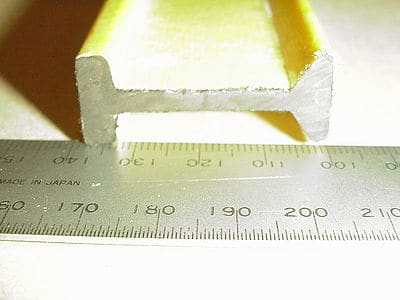
Materials used were 6mm (1/4 inch) aluminum rod for the directors, 6mm copper tube for the quad elements, 6mm polycarbonate (LEXAN) sheet for the quad spreaders, pultruded fiberglass boom, the machined aluminum bar for director mountings.
The photo shows a section of the boom material. This was sourced from Pacific Composites in Melbourne, Australia. It is used as the support section in fiberglass grate flooring used in harsh environments. (Price was approximate A$4.50 / metre early 1999). Being manufactured using the pultrusion process, it has a high ratio of glass fibers to epoxy resin. There is almost no flexing over a 3-metre length in the vertical plane and a minimal amount in the horizontal plane. The photo shows an end view of this material (on its side). This antenna has a boom length of 1950 mm.
I wanted this antenna to be portable, so the elements needed to be removable. I did this by machining bushes for the directors from a 19mm aluminum bar and glued these to the boom using epoxy resin. The following photos (hopefully) show enough detail of these bushes. The clamping screws happened to be some from the junk box, but anything with a diameter of about 3mm should do the job.
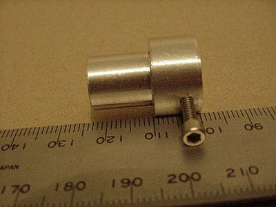
The third photo shows a bush with a director fitted. (There is a lack of definition in this one.)
2 Meter 8 Element Quagi all measurements in mm
- This page was created by Gary Bonnor – VK4ZGB. Updated 11 May 02
| 145.5Mhz | mm/100khz step (250 steps) | 147.0 Mhz | |
| Reflector | 2.2000= | 0.164 | 2.159 |
| driven element | 2.083 | 0.204 | 2.032 |
| Director 1 | 912.8125 | 0.00635 | 896.9375 |
| Director 2 | 908.05 | 892.175 | |
| Director 3 | 903.2875 | 887.4125 | |
| Director 4 | 898.525 | 882.65 | |
| Director 5 | 893.7625 | 887.8875 | |
| Director 6 | 889 | 873.125 |
HI
I´ve recently erected a 40 m delta loop and I was thinking on adding a yagi director for more gain, since I don´t have enough space to accommodate another triangle on the tower but I can manage to add a linear 1/2 wavelenght element. Do you think it can work?
of course
I came across your site when looking for antenna design software, and the Quagi sounds like an interesting design. My antenna application is not for amateur radio, but for fringe area mobile phone use at about 1GHz. I wondered if you had any comments on the use of this design at higher frequencies?
Also in you picture above (400px-Quagi_element1.jpg) the feed line is entering from ‘below’ the element (beneath the antenna) and I was wondering if you had experimented with feeding from ‘above’, (ie: running the feed line along the boom and ‘down’ to the feed point)?
Any idea what the wind load or surface area is on the 144mhz and 432mhz quagis??? I’m putting up a short 28 foot Rohn 25G soon and just planning ahead. I’ve already built the 6M and 20M yagis.
Greetings from Cornwall
I have an 8 el Quagi 2m made from various bits and bob boom is plastic conduit and wood re enforced but its coming to end of its life.
Now wanna take it one further and use 6mm ali tubing as the elements all that is and the boom is a boxed 25mm ali. BUT elements will be isolated form the boom.
How does one go about recalculating the element lengths and spacing etc please. if this is via that putta thing I have ain’t got a clue LOL
Last couple years had a lot of fun with me old Quagi beam and reached many places such as Spain France and around UK but not Scotland as yet.
Thanks again for the time and effort
Karl 2E0FEH
Has anybody built a dual band quagi for 2m & 70cm SSB? I’m thinking of 10ft. square fiberglass boom and build on that. I live in a deed restricted area and as long as i keep everything out off sight I have been good.
TNX.
@Richard
What did you use for your spreaders and Hub?
Nice piece of construction