Resistance and Resistivity
Resistance (R) is the measure of how much an object – a resistor – opposes the flow of electric current. The resistance of an object is measured in Ohms (<math>\Omega</math>)
Resistivity (<math>\Rho</math>) is a measure of how strongly a material opposes the flow of electric current. Resistivity is measured in ohm meters (<math>\Omega</math>m). Related wiki page: table of resistivities
The relationship between resistance and resistivity is:
- <math>R = {l \cdot \rho \over A} \,</math>
where
- <math>l</math> is the length of the object
- <math>A</math> is the cross-sectional area of the object (assuming constant), and
- <math>\rho</math> is the resistivity of the material
- <math>R</math> is the resistance
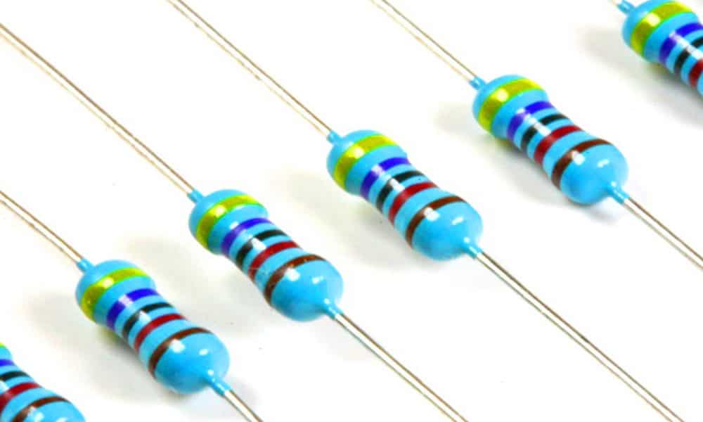
Resistors
A resistor is a passive electrical device that has been manufactured specifically to add resistance to a circuit, to effect a voltage drop.
The mathematical equation that describes the relationship between resistance, voltage drop and current through a resistor is known as Ohms Law
- <math>I = \frac{V}{R}</math>
where
- “I” is the current in amperes,
- ” V” is the potential difference between the ends of the resistor in volts, and
- “R” is the resistance of the resistor, measured in ohms
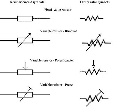
Resistor circuit symbols
Resistors in series and parallel

Total resistance in a series circuit: <math> R_\mathrm{T} = R_1 + R_2 + R_3 </math>
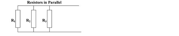
Total resistance in a parallel circuit: <math> \frac{1}{R_\mathrm{T}} = \frac{1}{R_1} + \frac{1}{R_2}+ \frac{1}{R_3} </math>
<math> R_\mathrm{T} = R_1 \| R_2 = {R_1 R_2 \over R_1 + R_2} </math>
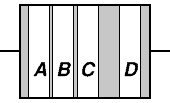
Resistor colour bands
The resistance of a resistor is coded into a series of coloured bands along its length:
- band A is the first significant figure of component value
- band B is the second significant figure
- band C is the decimal multiplier
- band D if present, indicates tolerance of value in percent (no color means 20%)
| Color | Band A | Band B | Band C (multiplier) | Band D (tolerance) | Temp. Coefficient |
|---|---|---|---|---|---|
| Black | 0 | 0 | ×100 | ||
| Brown | 1 | 1 | ×101 | ±1% (F) | 100 ppm |
| Red | 2 | 2 | ×102 | ±2% (G) | 50 ppm |
| Orange | 3 | 3 | ×103 | 15 ppm | |
| Yellow | 4 | 4 | ×104 | 25 ppm | |
| Green | 5 | 5 | ×105 | ±0.5% (D) | |
| Blue | 6 | 6 | ×106 | ±0.25% (C) | |
| Violet | 7 | 7 | ×107 | ±0.1% (B) | |
| Gray | 8 | 8 | ×108 | ±0.05% (A) | |
| White | 9 | 9 | ×109 | ||
| Gold | ×10-1 | ±5% (J) | |||
| Silver | ×10-2 | ±10% (K) | |||
| None | ±20% (M) |
Using the color code
For example, a resistor with bands Brown Black Orange Blue would have resistance 10×103 <math>\Omega</math> (10 000<math>\Omega</math>) with a tolerance of ±0.25%
Resistor types
Carbon composition
Carbon composition resistors consist of a solid cylindrical resistive element made from a mixture of finely ground carbon and insulating material. The mixture is held together by a resin, and wires are either embedded in the ends, or a thin metal cap and wire is attached to each end. The resistance is determined by the ratio of the powdered ceramic and the carbon. Higher concentrations of carbon result in lower resistance. These resistors are generally of high tolerance.
Carbon film
A spiral is used to increase the length and decrease the width of the film, which increases the resistance. Varying spiral shapes are used to create a variety of resistances.
Thick and thin film
Most SMD (Surface Mount Device) resistors are of this type. The principal difference between “thin-film” and “thick film resistors” is how the film is applied to the cylinder (axial resistors) or the surface (SMD resistors). In thick film resistors, the “film” is applied using traditional screen-printing technology.
Thin film resistors are made by sputtering the resistive material onto the surface of the resistor. The thin film is then etched to attain the desired resistance. They are then trimmed to an accurate value by abrasive or laser trimming.
By contrast, thick film resistors may use the same conductive ceramics as thin-film resistors, but they are mixed with powdered glass, and a liquid so that the composite can be screen-printed. This composite of glass and conductive ceramic (cermet) material is baked) in an oven at about 850 °C.
Metal film
A common type of axial resistor today is referred to as a metal-film resistor. MELF (Metal Electrode Leadless Face) resistors often use the same technology but are a cylindrically shaped resistor designed for surface mounting. [Note that other types of resistors, eg carbon composition, are also available in “MELF” packages].
Metal film resistors are usually coated with nickel-chromium (NiCr) but might be coated with any of the cermet materials listed above for thin-film resistors.
Wirewound
Wirewound resistors are commonly made by winding a metal wire around a ceramic, plastic, or fiberglass core. The ends of the wire are soldered or welded to two caps, attached to the ends of the core. The assembly is protected with a layer of paint, molded plastic, or an enamel coating baked at high temperature. The wire leads are usually between 0.6 and 0.8 mm in diameter and tinned for ease of soldering. For higher power wire-wound resistors, either a ceramic outer case or an aluminum outer case on top of an insulating layer is used. The aluminum cased types are designed to be attached to a heatsink to dissipate the heat; the rated power is dependant on being used with a suitable heatsink, e.g., a 50 W power rated resistor will overheat at around one-fifth of the power dissipation if not used with a heatsink.
Because wire-wound resistors are coils they have more inductance than other types of resistors, although this property can be minimized by winding the wire in sections with alternately reversed direction.
Foil resistor
Foil resistors have had the best precision and stability ever since they were introduced in 1958.
Resistor Circuits
Voltage Divider
Perhaps the most common use for resistors in a circuit is as a voltage divider:
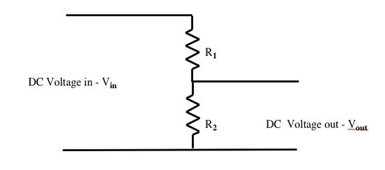
In this configuration, <math> V_{out} = \frac {R_2 \times V_{in}}{R_1+R_2} </math>