A filter is an electric circuit (often called a network) that allows certain frequencies to pass but rejects (attenuates) other unwanted frequencies.In general, filters are one of four types – Lowpass, Highpass and Bandpass (Notch) and Bandstop.
Filter Design
Low Pass (LP) Filter
A low pass filter is designed to pass low-frequency signals and to block those above a certain design frequency. In ham radio, these are typically used to block VHF harmonics of HF transmissions that interfere with TV reception.
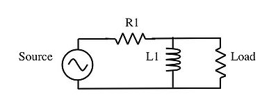
Inductive
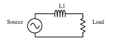
The impedance of the inductor L1 increases with increasing frequency. The increase in impedance blocks high-frequency signals from reaching the load.
Capacitive
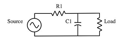
The impedance of the capacitor C1 decreases with increasing frequency. High frequencies are shorted out by this low impedance in parallel with the load. Most of the source voltage is dropped across the server resistor R1.
Which one do I use?
The inductive LP filter is often the preferred filter in AC – DC power supply design. It is used here because of its ability to filter out the leftover “ripple” created when AC is converted to DC in a Rectifier Circuits circuit. The addition of a series resistor in the capacitive LP filter is often undesirable in this application as it increases the internal resistance of the power supply circuit.
Capacitive LP circuits in situations where it is desirable for the resistive reactance is to be a minimum. In addition, capacitors tend not to “couple” with other components (generate interference in or receive interference from other components in the form of electric or magnetic fields).
What is cut-off frequency?
The cut-off frequency of a capacitive LP filter is the frequency above which the output voltage falls below 70.7% of the input voltage. For a simple capacitive filter as described above, the cutoff frequency is given by:
<math> f_{cutoff} = \frac{1}{2\pi RC}</math>
R = the resistance of the series resistor R1
C is the capacitance of the capacitor C1
High Pass Filter
High Pass filters allow the transmission of high-frequency transmissions and block frequencies below the design frequency.
Capacitive
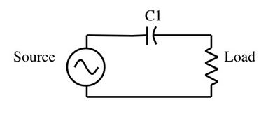
The impedance of the capacitor C1 increases with decreasing frequency. High impedance at the capacitor blocks low-frequency signals.
Inductive

The impedance of the inductor L1 decreases with decreasing frequency. Low-frequency signals are in effect shorted out by the inductor with most of the voltage from occurring at the series resistor R1.
the cut-off frequency of a high pass filter is the frequency below which the voltage across the load is 70.7% of the input voltage.
Band Pass Filters
Band Pass filters allow a specific band of frequencies to pass and block all those above and below. These are typically used in repeater installations to “notch” the frequency of the repeater and reject all unwanted frequencies.
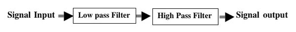
As the diagram above indicates, a bandpass filter is created by combining low-pass and a high-pass filter. Only desired frequencies are allowed to pass.
Capacitive
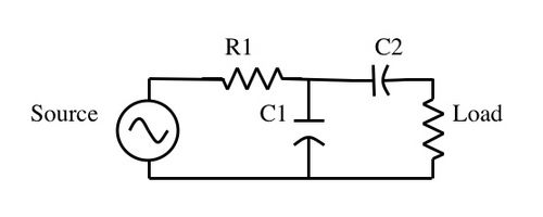
The components R1 and C1 fulfill the low-pass features of the filter. C2 then becomes the high pass section of the filter.
Inductive
Components R1 and L1 complete the high=pass section of the filter, while L2 filters out low frequencies.
Band Stop Filters
These filters block specific bands and allow those above and below to pass.
Filter Types
- Cavity Filter
- Saw Filter
- LC filters